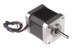
stepper motors
Why stepper motors are used in 3d printers?

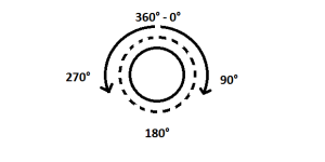
One of the main characteristics of stepper motors is that of being able to perform a complete rotation divided into small sections. A complete rotation means a movement of 360° from a starting point on a circumference.
To simplify the concept, let’s imagine that we can turn the shaft of our stepper motor by 1° at a time, to make a complete rotation we will have to “tell” the motor to operate 360 times always in the same direction.

These small movements are the “steps” and we can easily understand that the level of precision that we’re going to get is defintely high. The stepper motors that are used for 3d printers generally have steps of 1.8° which means that to make a complete rotation we will have to operate our motor 200 times (200×1.8° = 360°), therefore we have an excellent level of accuracy.
This precision is used to make really small movements with the moving parts of the 3d printer, this allows a remarkable level of accuracy and detail in our prints.
Another characteristic of the stepper motors, maybe the most important one, is that of being able to remain in a certain position, for example if we ask it for a movement of 10.8° it will stay in that position until we will ask him for a new rotation, ensuring constance in the reached position, which is decisive in the movements, especially along the “Z” axis of the 3d printers.
The low speed of rotation obtainable with a stepper motor allows us to fluently move even non-linearly, for example when the hotend has to draw a circle, in a Cartesian 3d printer this occurs by simultaneously moving the “X” and ” Y ” and the precision of the ring will be higher as much as the movement of the two axis will be fluid.

Identify the phases in bipolar stepper motors.
The stepper motors used in 3d printers are mainly bipolar, that is with four wires and their actuation is made by the passage of the current alternately in both directions to generate the magnetic field suitable to induce rotation with precision.
The four wires identify the four coils connected in pairs and it is not too difficoult to identify them. With a tester positioned to measure a resistance value, the pairs of wires connected must be found, that is, those that return a value on the tester.
We can assume that we have the 4 wires, green, red, blue and black and having identified the pairs with red / green and blue / black we can now find the suitable sequence to allow the correct direction of rotation.
With a power source, I usually use a simple well-charged 9V battery, let’s connect the first pair, for example red to positive (+) and green to negative (-) and we will notice a small movement of the crankshaft.
Then we will do the same thing for the second pair with blue to positive (+) and black to negative (-) and we will get the same direction of rotation of the motor.
If we’ve been lucky we will already have the right sequence which will be red-positive (+) / green-negative (-) / blue-positive (+) / black-negative (-) for the rotation in one direction and red-negative (+ ) / green-positive (+) / blue-negative (-) / black-positive (+) in the opposite direction, otherwise we will only have to change and check the correct color / pole association of one of the two phases.
if you want to know more, if you need help write to info@3deasy.it
if you want to be updated on the next article, fill in the following fields to subscribe to the newsletter.
